DMP Photo Booth: The Trigger
After several days of trying to make sense of the POSIX Terminal Interface, I’ve come to a lull in development. Today I’ve been looking through the code, fixing problems as I find them. One major problem I noticed: there is no documentation on the actual trigger.
I decided to draw a schematic for the trigger:

The Concept
It’s pretty basic: a button and 5 lights. My general concept for the trigger was inspired by the starting light at a race. It counts down from 5: at 5, the top light is lit, at 4 the top two are lit and so on. As the count reaches 1, all lights are lit and the camera module calls capture(), starting the race.
If an error needs to be displayed, the 5 lights act as the first 5 bits in a byte (it can display 0 – 31). The lights flash a binary number indicating the error that occurred. Practically, what will happen is a user will go tell a grownup that “it’s blinking”. But an operator can see the code and interpret the problem. The codes will be high level; actual error messages will get printed to the console. However, I felt it important to give negative feedback on the trigger so users don’t just sit there wondering why nothing is happening.
Room for Improvement
There are two things up for consideration at the moment. The first thing is the light configuration. I had a racing starting line in mind, but it turns out that the starting line of a race looks like this:
I guess I’m just not much of a racing fan… I may change the lights to match, or I may abandon my metaphor. Either way, this is a low priority issue.
Secondly, I am considering implementing an audio element to this. If I add this, the trigger will play a low-pitched tone on red lights, and a higher pitched tone on green. This will make it more obvious to the user that a countdown is happening. If you’ve ever played Mario Kart, think the noise the light makes at the starting line.
The only reason I haven’t already added this is because I’m concerned it may be annoying.
Ohm’s Helper: Scripting My Calculations
So, one day I found myself hunting for my calculator. I had been using the built-in calculator program on my laptop to calculate resistor requirements for LEDs, but I found myself craving the fancy formatting of my fancy graphing calculator. After digging through my backpack and office, I thought to myself “Aren’t you a programmer? Clearly it’s time for a script!”
Oh yes, there will be scripts…
Requirements
As I opened up gedit and began coding some boilerplate, I thought about what my script should do. There are two main calculations that I find myself doing lately:
My script will automate these calculations. I decided that I’d use the pretty menu input menu over command line switches. Switches are supposed to save you time, but I find that unless I’m using some utility all the time I always end up doing foo -? first. I decided to use Lua for my script; I like Lua’s simple syntax, multiple return values, and first class functions.
The Script
Full source code can be found on my github. Arduino Helper is licensed under the GPLv3.
Functions in my script return two values: a value, and a user-friendly message. If some error is encountered, the value is nil, and the message is the error. If all is well, a number is returned, and an output message to the effect of “You got 3 foos! Huzzah!” is displayed. This message is printed at the end, and the value is largely unused at this time. I figure as I expand the script, a value will be nice to have to pass around to other functions as I add them.
Ohm’s Law
Four functions make up the Ohm’s Law calculations:
local function res(i, v)
	return v / i, "V / I = " .. v / i .. " Ohms"
end


local function amp(r, v)
	if r == 0 then return nil, "R must be greater
					than 0!" end
	return v / r, "V / R = " .. v / r .. " Amps"
end


local function vol(r, i)
	if r == 0 then return nil, "R must be greater
					than 0!" end
	return r * i, "R * I = " .. r * i .. " Volts"
end


local function ohms_law(i, r, v)
	if i == nil then return amp(r, v)
	elseif r == nil then return res(i, v)
	elseif v == nil then return vol(r, i)
	else return nil, "i, r, or v must be nil!" end
end
Res, amp, and vol are pretty self-explanatory, but ohms_law bears some explanation. Ohms_law takes 3 arguments: i, r, and v. It expects one of these to be nil. This is the value that it is solving for. Depending on which one is nil, it calls amp, res or vol.
LED Resistor Calculation
The LED calculation is handled by one function:
local function led_calc(supply, led_vol, led_curr,
					quantity)
	local v = (supply - (led_vol * quantity))
	if v <= 0 then return nil, "Insufficient supply
					voltage!" end
	return res((led_curr / 1000), v)
end
This function is also pretty straightforward: it takes the supply voltage, LED voltage, LED current, and quantity of LEDs, and applies Ohm’s Law to calculate the resistance (by calling res).
It does check to ensure that supply – (led_voltage – quantity) is greater than or equal to zero.
Fancy Menus
…and of course, we have our fancy menu. This is handled by one big function, with two nested functions:
local function director()
	local function gather_law()
		local r = nil
		local i = nil
		local v = nil
		print("\nSolve for:")
		print("1) R")
		print("2) I")
		print("3) V")
		local selection = io.read("*n")
		if selection ~= 1 and selection ~= 2 and
				selection ~= 3 then
		return nil, "Invalid Selection!" end
		if selection ~= 1 then
			print("Enter R in
				units of Ohms:")
			r = io.read("*n")
		end
		if selection ~= 2 then
			print("Enter I in
				units of Amps:")
			i = io.read("*n")
		end
		if selection ~= 3 then
			print("Enter V in
				units of Volts:")
			v = io.read("*n")
		end
		return ohms_law(i, r, v)
	end
	local function gather_led()
		local supply = nil
		local led_vol = nil
		local led_curr = nil
		local quantity = nil
		print("\nEnter the Supply Voltage:")
		supply = io.read("*n")
		print("Enter the LED Voltage:")
		led_vol = io.read("*n")
		print("Enter the LED Current in
				units of Miliamps:")
		led_curr = io.read("*n")
		print("Enter the amount of LEDs:")
		quantity = io.read("*n")
		return led_calc(supply, led_vol,
				led_curr, quantity)
	end
	print("Select your calculation:")
	print("1) Ohm's Law")
	print("2) LED Resistor Requirement")
	local selection = io.read("*n")
	if selection == 1 then return gather_law()
	elseif selection == 2 then return gather_led()
	else return nil, "Invalid Selection!" end
end
This function handles all menu operations. I felt it would be good to keep calculations and menus separated into separate functions, so that if I want to reuse the calculation functions, I don’t need to worry about refactoring anything. Therefore, I have director, gather_led, and gather_law.
Director requests the user select a calculation to perform, and then returns a call to gather_led or gather_law. The gather functions handle information gathering, then returns a call to the appropriate function. Long story short: the result of the calculation functions are returned to the caller of director.
Learning to Arduino: the LED
…and now for something a little more basic: the LED. Those little blinky lights that keep us up at night. What electronic device is complete without them?
The Basics
LED stands for Light Emitting Diode. Yep, like that. Luckily for us, we don’t need to muck about with I/V curves; we only need to know three things to set up our LEDs: the supply voltage, the LED voltage, and the LED current. These values should be provided on the packaging for your LED, on the vendor’s website, or on the datasheet.
Supply voltage
This is the voltage provided by your power source. If you’re using an Arduino, it will be 5 or 3.3 volts. If you’re using some other power source, it will be the value provided by your power source.
LED voltage
This is the voltage ‘consumed’ by the LED. Say you’re using one 2 volt LED, your supply voltage must be higher than 2. If you’re using two 2 volt LEDs, your supply voltage must be higher than 4. If your supply voltage does exceed the combined LED voltage, none of your LEDs will light up.
LED current
This is the safe operating current for your LED. If your current is low, the LED won’t light. If your current is high, your LED will burn out. It is really easy to destroy your LED, so don’t just do whatever and hope everything will be fine; it won’t be and you’ll be out $0.35.
Wiring it Up
So, you’ve got your supply voltage, LED voltage, and LED current, what now? In order to get our current down to the LED current, we need to use a resistor. In order to calculate what resistor to use, we need to use Ohm’s Law. Specifically we need to calculate the resistance by dividing:
R = (Supply voltage - LED voltage) / (LED current / 1000)LED current will be given in units of miliamps, therefore we must divide it by 1000 to get the amount in amps. This formula will give you a value in Ohms. For example, I have an LED with a LED voltage of 2.2, and an LED current of 17 miliamps. I will be powering this using a digital output pin on my Arduino Uno, which outputs 5V. Doing the math:
(5 - 2.2) / (17 / 1000) = 164.706What’s that; you don’t have a 164.706 Ohm resistor? That’s fine, just use one that is close. Pick one that’s a little high, rather than one that’s a little low; better to not have it light up than to burn out. I’m going to use a 180 Ohm resistor.
Now that we know what resistor to use, it’s time to hook it all up. You should wire it up like so:

Note that your LED will have two legs: one will be shorter than the other. The long leg should be hooked up to positive, the short leg should be hooked up to negative. If they are reversed, your LED will be reverse-biased, and won’t light up. This is another good way to potentially destroy your LED.
Open up NetBeans, which I’m assuming you configured for arduino, and create a new arduino project. We’re not doing anything fancy today, we just want our pin to output. Your implementation should look like this:
#include <Arduino.h>
extern HardwareSerial Serial;
int led = 13;

void setup() {
	pinMode(led, OUTPUT);
}

void loop() {
	digitalWrite(13, HIGH);
}
Upload your project and, assuming all is well, watch your LED light up!
That Sounds Like a Lot of Math…
Yep. Pretty much. Luckily there are calculators on the internet for figuring these things out. Here’s a nice one that I found while researching this blog post. Feel free to never figure this out on your own again.
Learning to Arduino: the Diode
So, what is a diode? A diode is an electrical component that allows current to flow in one direction, but not another. On an electrical diagram, a diode is represented by this symbol:

The physical diode may have a black band on it, this band corresponds with the band on the symbol. One use for a diode is to protect against the power source being hooked up backwards. Let’s look at an example.

In this diagram, the diode is hooked up backwards. This configuration is said to be reverse biased. In this configuration, ‘no’ current will flow across the circuit. In fact, if the current exceeds the diode’s Maximum Repetitive Reverse Voltage (VRRM), the diode will be damaged. This value can be found on the diode’s datasheet. When I say ‘no’ current flows in this configuration, I actually mean a negligable amount of current flows. More on this in a minute.
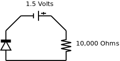
In this diagram, the diode is hooked up in the correct direction. This configuration is said to be forward biased. In this configuration, current will flow across the circuit. How much current? Well, according to Ohm’s Law:
1.5 Volts / 10000 Ohms = 0.15 MiliampsBut let’s check just to be sure… If we set our multimeter to amps, and we measure, we get… 0.1 Miliamps… …that doesn’t seem right…
Well, the bad news is that it is just one post into this series, and we’ve already come across an exception to Ohm’s Law. To figure out the current across a diode, we need to use the Shockley Ideal Diode Equation. Do yourself a favor: don’t waste your time trying to figure this out. Just use the Voltage/Amperage curve graphs provided on the datasheet for your diode and save yourself a headache.
Therefore, you will see a somewhat level amount of current flowing through your diode, then suddenly it will shoot up. If this happens, it’s time to consider that you need a different diode.
