DMP Photo Booth 1.0
Well, the day has come and gone. DMP Photo Booth’s final test on June 21st went off without issue, and DMP Photo Booth has left Beta and is now considered “production ready”. The initial 1.0 release can be found on GitHub.
The significance of June 21st is the very reason DMP Photo Booth was created; the 21st is the day of my wedding. My wife wanted a photo booth for the reception. We looked into renting a photo booth, but it turns out that they run around $1,000. I turned to open source. Some quick googling turned up some options, but they were all personal projects or out of date. Sure I could get somebody else’s project working, but what’s the fun in that? I decided that we didn’t need to rent one, or download one, I could build it!
In late 2013, I set to work in earnest. I had a couple of months of downtime in school, and since I’m not currently working it was the perfect time. I decided I had three main objectives for this project: get some arduino experience, get some GTK+ experience, and do this all as portably as possible. I had initially decided to mostly ignore GLib and focus on GTK, but slowly I grew to appreciate GLib for what it is: the standard library that C never had. First I used GModule to handle shared libraries in a portable manner. Next I decided to use GLib primitives to keep from having to deal with cross-platform type wonkiness. Next, having grown tired of dealing with return codes, I refactored the project to use GLib’s exception replacement: GError.
Lessons Learned
It’s not all roses and puppies though. There are certainly things I’d do differently. DMP Photo Booth is developed in an Object Oriented style, passing opaque structs with “method” functions that operate on them. Each component of the program are organized into their own source file with file scoped globals scattered throughout. Said globals are protected by mutexes to create a semblance of thread safety. That said, threading issues have been a major thorn in my side. Long story short: I regret this design choice. While I still feel that this is the correct way to structure C code, and that if globals are required, this is the correct way to handle them; I feel that I should have made more of an effort to limit side effects. Recently, I’ve spent some time doing functional programming, and if I could do it again I’d try to write in a more functional style. Fortunately for me, this is something that a little refactoring could help with.
Additionally, one thing I thought would be a major help is something that began to be a major thorn in my side: NetBeans. As the size of the project grew, NetBeans got slower and slower. It seemed that I spent more time fiddling with IDE settings than actually coding. Even worse is that the IDE-generated makefile is so convoluted that it’s extremely difficult to modify by hand in a satisfying way. I’ve always coded with and IDE so I wouldn’t have even considered not using one, but then I spent some time with Haskell. One of Haskell’s “problems” is that it doesn’t have good IDE support. It doesn’t seem like any IDE really handles it well, so most people use Emacs. Personally, I haven’t really warmed up to Emacs, but GEdit has syntax highlighting for Haskell and a built-in terminal for GHCI. GEdit also has syntax highlighting for C. Next time, I will seriously consider using a lighter-weight text editor for a C project. All this said, I think NetBeans for Java remains the way to go.
What’s Next
Like any program, version 1.0 is just one of many versions. There certainly remains a lot of work to do with DMP Photo Booth. Some major items you are likely to see whenever I get around to working on DMP Photo Booth some more:
Options Dialog
I think anybody who has seen it will agree: the options dialog in DMP Photo Booth is bad. It’s poorly organized, and kind of wonky. Personally, I modify settings using the .rc file, which is telling. This is certainly a high-priority improvement.
Functional Refactor
Like I said above, the code could use a pass to limit side effects. Funtions need to have their side effects limited, and globals need to be eliminated unless absolutely necessary. However, C is not a functional language. While one could argue that function pointers enable functional programming in C, this is a very pedantic argument. I won’t be going crazy with functional programming techniques. There will be no Monads, or for loops being turned into mappings of function pointers.
Optional Module API
An idea I’ve had on the back burner for a while is an optional module API. This would be used for very specific quality-of-life things. For instance, a module could provide a GTK widget to be shown in the options dialog. Any module that doesn’t want to implement any or all of the optional API can just ignore it. The module loading function will gracefully handle the dlsym failure, just treating it as it is: declining to implement the API. I have no plans to change the current existing API, so all you module developers can rest easy!
User Interface Module
It occurred to me that it might be good to have a UI module. This would provide the UI, and wouldn’t be tied to the trigger/printer/camera module start/stop system. This module would be loaded at startup and unloaded on shutdown. This would allow the Photo Booth to use different widget toolkits: QT, Curses, Cocoa, WinForms, or whatever else. Under this scheme, the current GTK+ interface would be abstracted into the reference UI Module.
DMP Photo Booth: Release Candidate 1
It’s been a long time coming, but the day is almost here: the day DMP Photo Booth is officially released.
Following last week’s successful stress test, I’ve been doing some last-minute touch-up work. I’ve been preparing my laptop for the big day, and finding and squashing some bugs.

DMP Photo Booth RC1 using my fancy new dark GTK theme
Now things are coming along, and I feel the time has come to proceed to RC1. This means that barring any major new show stoppers, DMP Photo Booth will proceed to version 1.0 on June 22.
You can find the latest release here. On that page you’ll find the latest source for DMP Photo Booth and the reference modules, as well as a pre-compiled version for Debian/AMD64. Just extract the tarball into a folder and double-click the executable and you’re off! It comes pre-configured with sane defaults.
Moving forward, I plan to work on a “GTK Trigger Module”. This will just show a window with a button you can click to trigger the photo session. I understand that not everybody feels like constructing an Arduino thingamabober, and that this is surely the only thing preventing DMP Photo Booth from going viral on a global scale. Hopefully this is done by 1.0, but if not it will likely make it into a version 1.0.1, to be released shortly after 1.0.
DMP Photo Booth: Crunch Time
Over the last few months, I’ve become distracted. As anybody who’s ever committed to one project can probably tell you: it stops being exciting. What was once your pride and joy becomes the daily grind. Things get stale. As was the case with me, I suspect that this happens for most people when development of new features ends and the focus shifts to bug fixes.
I became distracted. My mind began to wander to the next thing, which in my case ended up being Haskell. I began learning Haskell, and it was definitely educational. I learned a lot with Haskell, and I plan to stick with it so that when I list it on my resume, I don’t get destroyed on a whiteboard test. Then came The Great Matrix Affair of 2014; I got overwhelmed at school. I spent so much time studying and doing homework that I couldn’t muster up the motivation to program. Things fell by the wayside, as you can see in my blog post output for February. Luckily for me, that is done, and I have the next two months free to program!
What Remains To Be Done?
It’s been a good 6 – 8 weeks since I’ve really focused on DMP Photo Booth, so the first order of business is the figure out what needs to get done. After doing some brainstorming I’ve settled on a list:
Finish The Trigger
I’ve mostly completed the trigger, but it doesn’t work. The button is soldered wrong, and while it was magically working for a while, it has since stopped. I need to fix the wiring issue, and then drill a hole in the box to put it through. After that and maybe a quick coat of paint it will be complete.
This particular task is due by Friday. I have a series of VIP demos coming up, the first of which is Saturday morning. A few of my cousins are coming in from out of town on Saturday to do wedding stuff, and I want to show it off then. While my cousin Allen is an engineer, and can appreciate a breadboard mockup of what will Totally Become A Real Thing, it certainly won’t be impressive. My cousin Laraine will likely be less amused, but I’m sure I’ll get a pat on the head for my “hard work”. Due to this, it’s important that the trigger be done before then.
Facebook Printer Module
The reference suite of modules was planned to be: a Trigger Module using my Arduino implementation, a Printer Module using CUPS, a Camera Module using LibGPhoto2, and a Lua module for each so that modules can be created using Lua. Of these, only the Lua Printer Module remains to be done. Since creating a Lua module is a trivial task (and not terribly important to be honest), this is a very low priority item.
However, the current Printer Module requires a physical printer. This might not always be ideal, since printers are big and heavy. What if you just want to bring a laptop and a camera and have a photo booth? My fiancée is having just this sort of situation; she wants to use the photo booth at her bachelorette party, but who wants to lug a huge printer to a hotel room? To solve this, I’ve promised her a Facebook Printer Module.
The idea is that when dmp_pm_print() is called, the photo strip will be uploaded to facebook. While I know this sort of thing can be done, I haven’t really researched it much. If it turns out that you have to pay facebook money to get this sort of access, I will find a hosting service that is free. Maybe Photobucket, or Dropbox, or whatever. The important thing is that the photo strips will end up in some central location on the internet so that anybody at the party can download the strip later. Ideally, this central location would be a facebook gallery so people can tag themselvs and be all Web 2.0.
My fiancée’s bachelorette party is in May, so this project isn’t a burning priority. However, this represents the most substantial addition of new functionality remaining to be done, so I plan to work it sooner rather than later. Code will be posted on my Github as it evolves, and like DMP Photo Booth will be available under the GPLv3.
Mac Support
To this point, all my development has been done in Linux. First using Ubuntu, and now using Debian. However, most people don’t use Linux. While Linux is the main target platform for DMP Photo Booth, I have been coding as portably as possible, so it should be little effort to port the application to Mac. Over the next few months, I’ll be making sure it compiles and runs correctly my old Macbook. My Macbook is vintage 2010, as such it is only running Snow Leopard. Therefore if anybody in the audience is a Mac user, and has a current version of OSX, feel free to give it a shot as well and let me know how it goes.
Ideally, my fiancée will bringing the Macbook to her bachelorette party and not my development laptop, therefore this project is due at the same time as the Facebook Printer Module, in May.
Bugs!
Finally, bugs. I need to identify them. I need to squash them. And I need unit tests.
After making a big show about being a good person and doing unit tests, I promptly lost the faith. Soon after implementing those first tests, I made a major change to how I handled errors in my code. Suddenly, all my tests were broken, and I was faced with the choice: rewrite them all, or delete them. After some thought I decided that my tests weren’t that great and that I’d probably change something again and break them all again. So I deleted them.
I’ve got to say, I miss those tests. There has been more than a few times where I’d refactored something and wasn’t sure if it still worked. Sure, it seems to work, but does it really? If I had unit tests in place, I could say with a greater degree of certainty that they do. Plus, “it sounds like a lot of work” is not a good reason not to do something, so it won’t be one for me.
On top of that, I’ll be identifying and squashing bugs the old fashioned way: by trying stuff. I’ve already found a few doozies, and I’m sure I’ll find more. As I find them I’m going to post them on the bug tracker for DMP Photo Booth on Github. I do this for a few reasons: 1) it will provide a public centralized repository of open issues so that I don’t lose or forget about them. 2) I would like others to post bugs here. If I post them here and show that I am fixing them, I feel it will establish confidence that it is looked at and acted upon.
This is due when DMP Photo Booth goes to version 1.0. That is planned to be on June 21, the day of my wedding. DMP Photo Booth will get a good solid night of work as the 80 or so people attending put it through its paces. Assuming all goes to plan with minimal issues, DMP Photo Booth will be declared to be out of Beta. That said, to be truly version 1.0, unit tests must be in place and “all bugs must be fixed”.
Packaging
Currently, DMP Photo Booth is available in source form only. No end-user ever had to compile Microsoft Office; I don’t feel they should have to compile DMP Photo Booth.
To that end, binary distributions will be available for Linux and Mac when DMP Photo Booth goes to version 1.0.
Got My Work Cut Out For Me
It’s a long list to be sure, but I have 4 months to focus on it. However, I’ve decided that I should spend some time focusing on other things too, so that I don’t burn out. To that end, I plan to spend 1 day per week focusing on learning new technologies, and 1 day per week keeping my old skills sharp.
For new technologies, this means things like learning more Haskell, and other languages or frameworks. Whatever strikes my fancy. For old skills this means practicing with Lua and Java, and maybe even C++ if I’m feeling particularly masochistic that day. This will likely take the form of blog posts on topics relating to these, so stay tuned!
DMP Photo Booth: The Trigger
After several days of trying to make sense of the POSIX Terminal Interface, I’ve come to a lull in development. Today I’ve been looking through the code, fixing problems as I find them. One major problem I noticed: there is no documentation on the actual trigger.
I decided to draw a schematic for the trigger:

The Concept
It’s pretty basic: a button and 5 lights. My general concept for the trigger was inspired by the starting light at a race. It counts down from 5: at 5, the top light is lit, at 4 the top two are lit and so on. As the count reaches 1, all lights are lit and the camera module calls capture(), starting the race.
If an error needs to be displayed, the 5 lights act as the first 5 bits in a byte (it can display 0 – 31). The lights flash a binary number indicating the error that occurred. Practically, what will happen is a user will go tell a grownup that “it’s blinking”. But an operator can see the code and interpret the problem. The codes will be high level; actual error messages will get printed to the console. However, I felt it important to give negative feedback on the trigger so users don’t just sit there wondering why nothing is happening.
Room for Improvement
There are two things up for consideration at the moment. The first thing is the light configuration. I had a racing starting line in mind, but it turns out that the starting line of a race looks like this:
I guess I’m just not much of a racing fan… I may change the lights to match, or I may abandon my metaphor. Either way, this is a low priority issue.
Secondly, I am considering implementing an audio element to this. If I add this, the trigger will play a low-pitched tone on red lights, and a higher pitched tone on green. This will make it more obvious to the user that a countdown is happening. If you’ve ever played Mario Kart, think the noise the light makes at the starting line.
The only reason I haven’t already added this is because I’m concerned it may be annoying.
Learning to Arduino: Push Button
Getting a little less abstract today, I’d like to talk about the Push Button. Sorry, that doesn’t have a fancy name. Try to contain your disappointment.
The push button is actually very simple in theory. Most push buttons have four contacts. Two of these contacts are connected at all times, and there is a normally open switch between the two “wires”.

When the button is pressed, the contact closes. The tricky part comes in the implementation.
pinMode(pin, INPUT): REVEAL YOUR SECRETS!
You’d be yelling too if you’d spent as much time as I trying to figure this out.
A typical application of the Push Button, is in an arduino device. Arduinos have multiple digital pins that can be configured as inputs or outputs. Google Arduino Push Button Tutorial, and you’ll find several tutorials that suggest you implement something similar to this:

The thing that nobody is talking about: what is the voltage of the digital pin in input mode. This is the thing I’ve been spending the last few hours trying to figure out: how does this work? If the voltage is 0, nothing should happen when the button is not depressed. If the voltage is 5, then nothing should happen when the button is depressed. It turns out, according to my multimeter, that this pin is actually very slightly less than 0 Volts.
As you can see from my diagram, the digital pin is connected to the switch, and the opposite end is connected to a 10K Ohm resistor to ground. On the other side of the switch is 5 Volts. When the switch is open, electrons flow from ground (0 Volts) to the input pin (slightly less than 0 Volts) and digitalRead() returns LOW. When the Push Button is depressed, electrons flow from the input pin (slightly less than 0) to the 5 Volt pin, and digitalRead() returns HIGH.
All is again well in the world.
DMP Photo Booth: First Commit
Well, it’s been a long time coming, but this weekend 45 days of work has culminated in my first milestone: DMP Photo Booth has received its first commit. If you go to this page, you’ll find the newly created Github repository for it. Feel free to go judge all the choices I made, I’ll wait…
…done? Good, now I’d like to use this post to talk about it.
The Story So Far

So far, most of the work is done in the core. There are module stubs for each module, and they are loadable and “function”, but they don’t do much of anything. However, the UI for the core is, for the most part, done. If you build the core (Either open the projects in NetBeans or cd into its directory and enter make build), and run it (as of this writing, it must be run from the project root directory, since the supporting files are located here and referenced by relative paths) it will launch. At this point, you can launch the about window, the config window, or exit the program. From the config window you can load your modules (built stub modules are included for your convenience), and the status indicators on the main window will detect it.
All this is fine and good, but the real story here is the plumbing that has been laid.
Said Plumbing
Not much works at the moment, but the groundwork has been laid for things to come. Going down the list:
Global Defines
In this header, you’ll find all the magic integer constant return values used throughout DMP Photo Booth and friends. I touched on this topic briefly in a previous post, but the cliff’s notes version is that I feel that using a bare integer instead of an enum reduces the burden on module developers, and that the benefits of an enum aren’t great enough to justify this burden.
As this header has no accompanying .c file, it can be #included by module developers so they can make use of it if they like. I do this in my modules.
Module
One of the first things I worked on was module handling. This header holds all the functions required for the loading and unloading of modules, and the calling of module functions. At first I was implementing all of this with POSIX calls, but it occurred to me that I was defeating the purpose of my modular architecture by using non-portable calls. For this reason, I switched to GModule for module handling. I wrote a post about this if you want to hear more.
Module Callbacks
This header contains functions that will be added to modules as callbacks. Currently, this is the function that will be called when the user presses “the button”, and the function that will be called to push a message to the console queue.
Error Handling
My general approach to function design is that functions should not return void. All functions that would, instead return gint. This way, I have a mechanism to detect error conditions. In a language without Exception Handling, this is a nice thing to have. This header contains functions to extend this. Since sometimes you can’t return gint, I’ve created a facility to log error codes, similar to how the POSIX errno function works.
Console Queue
This header contains a thread safe queue to store messages to print to the console. Currently, this is implemented with a GQueue and mutex locking, but I made that choice before I knew about GAsyncQueue. I may refactor this at some point to use GAsyncQueue, but for now it works fine, and I see no immediate issue with my implementation.
The idea behind the console queue is that there should be a generic way to store messages. Currently the console is a GtkTextBuffer, but if I build around this, it limits future functionality. Suppose I wanted to support a command line only option? It’d be silly to require GTK for that, wouldn’t it?
That said, the default implementation uses a function placed in the GtkMainLoop to pop all messages out of the queue and place them into the GtkTextBuffer.
Module Status Watchdog
This header file is in charge of keeping those fancy module status indicators up to date. There are two main moving parts here: a thread that polls the module status, and a function run by the GtkMainLoop.
The Thread polls the modules every 3 seconds and pushes any status changes to a GAsyncQueue. Meanwhile the GtkMainLoop checks the GAsyncQueue for updates, and sets the indicator status accordingly. Why doesn’t the GtkMainLoop just check the module status you ask? I wanted to make sure the GtkMainLoop does as little work as possible. Currently the calls to check module status are pretty trivial, but there is no guarantee that they will stay that way. Since nobody likes an unresponsive interface, I kept them separate.
User Interface
This rather hefty header contains two things: a function to build and launch the UI, and all the callbacks called by said UI. All the callbacks are named according to their glade widget name to maintain some semblance of readability.
The Next Step
Obviously, looking through the User Interface source, there are signals to be hooked up. But aside from that, the core is coming along. The one big portion of the core remaining to be done is the photo booth strip logic. The camera module will take X pictures and download them. At this point it is up to the core to assemble them into on image file to be printed.
For now, I will continue to hook up signals and refine the existing portions of the core. While I do this, I will research image handling libraries. I’d like to keep things within the GLib family, but failing this, I will try to keep it limited to libraries shipped with Ubuntu (The default platform). Windows compatibility will come, but version 1.0 will work on Ubuntu.
Also looming on the horizon are the modules. I have a general idea of how I will deal with these, but nothing is set in stone. The first module that I will likely handle is the trigger module. I plan to implement the trigger module using Arduino. This is a topic that interest me, but I’ve never had a good project idea. Whenever I get tired of dealing with GTK, it should be a nice change of pace.
Introducing DMP Photo Booth
In June of 2014, I will be getting married. One problem: I am currently an unemployed student, and my fiancee Liz is also between jobs. Recent studies show that the average couple in this day and age spends an average of Twenty Four Bajillion Dollars on their wedding. Capital Bajillion. Italicised. Even were I still employed, this would pose a problem for me. Needless to say, we began looking for costs to cut. Liz really wants a photo booth, and I think it sounds fun. Unfortunatley photo booths run from $750-1000 to rent. The solution: DMP Photo Booth.
On Reinventing The Wheel
DMP Photo Booth wasn’t actually my first thought. That would be “well, there must be some open-source photo booth software we can use!” It turns out that there is. People like me who’ve had this issue and whipped something up for themselves. Some of these projects even have fancy websites. Unfortunately, none of these seem to have reached the level of maturity where you can just grab them and go. No, we’re talking old-school Linux status projects. If I’m going to have to put that much effort into making this work, I might as well roll my own. Besides, it will be good experience.
Requirements
The photo booth must do the usual photo booth stuff; it should programatically take 3-4 pictures, arrange them in a vertical strip with a background picture, and print them on photo paper. This should all work with the user only having to press a button(not a key on the laptop, an actual button), and there should be some sort of indicator when the pictures are going to be taken.
Some reasearch turns up the existence of a Picture Transfer Protocol, or PTP, that has been “supported” by the major camera vendors since 2002 or so. PTP allows you to programatically control a digital camera, and should serve nicely. I own a printer that can print on photo paper; it seems likely that I will be able to use the operating system’s printing facilities to handle this. Finally, I will construct a button and indicator thingamabober using Arduino.
Architecture
I have decided to go with a modular architecture. There will be four components: a Camera Module, a Printer Module, a Trigger Module, and the Core Application.
Core
The Core Application will bring the GUI, tenatively planned to be implemented using GTK+3, and will interface with the component modules. The core expects the component modules to implement specific functions that will be called to handle their operation. The component modules will be dynamic libraries that can be swapped out at runtime.
Camera Module
The Camera Module will handle the operation of the camera. The Camera Module currently is expected to implement two functions:
int dmp_cm_capture();
int dmp_cm_download(char * location);
These two functions do what they say: the first takes a picture, and the second downloads the picture to the passed-in path. The reference Camera Module will use libgphoto2 to implement these functions, but this module exists to provide the capability to use any method. A module that uses some other PTP library, or some custom protocol, or a dummy module that uses a picture on the filesystem, or uses a scanner, or anything else can be swapped in at runtime and this will all be transparent to the Core.
Printer Module
Shockingly, the Printer Module will handle printing. The Printer Module is currently expected to implement one function:
int dmp_pm_print(char * to_print);This function prints the file at the path that is passed into the function. This module prevents the Core from needing to know how to print. The Core tells the Printer Module to print, and the Printer Module can figure out how to print in Linux, or Mac OSX, or how to print to a Game Boy Printer, or whatever. The Core doesn’t care.
Trigger Module
The Trigger Module is the module that knows how to operate the custom photo booth equipment. The Trigger Module currently is expected to implement two functions:
int dmp_tm_add_trigger_handler(void (*th)());
int dmp_tm_set_countdown(int current);
The first function adds a callback function that will be called by the Trigger Module when it detects that the button has been pressed. The second function updates the countdown indicator. Since some dealybopper that I made out of Arduino is basically the definition of non-portable, I decided to create a module for it. The reference implementation will be written for my equipment, but this module can be replaced with one that uses some other input device with minimal effort.
Moving Forward
DMP Photo Booth represents my first major open source project, and it has many moving parts. With this groundwork laid, I have broken the project down into more manageable chunks. I have four main components that each represent different challenges: GUI programming in the Core, poorly documented mystery libraries in the Camera Module, Learning to Arduino to finish the Trigger Module, and learning the Linux printing system for the Printer Module.
Rome wasn’t built in a day, but it was started in one. There will surely be many challenges and roadblocks on the way. Expect to hear all about them here!
The Case of the Missing Tip
For the past 10 years or so of my career, I’ve mostly been employed as a sysadmin. During this time, I spend a great deal of time working with Solaris 10. Solaris 10 has a command called tip. Tip can be used for basic serial communications. You basically just pass it a baud rate, and a serial device, and it connects the STDIN and STDOUT.
Working with Arduino, sometimes you want to connect to the serial port and communicate with it. There is a whole Serial library for reading from and writing to Arduino via the usb cable. The Arduino IDE also comes with a serial monitor for use. However, using NetBeans, I find it kind of silly opening Arduino IDE just to use the serial monitor. Unfortunately, tip seems to be a Solaris-only utility. At a loss, I turned to google.
Google Proves Unhelpful
Shocking, I know. The number one solution to this is “Well, just write something in C!” I know what you’re thinking, and yes it did occur to me that this would be right up my alley. However, I know there is a utility that exists that does exactly what I want. In the interest of not re-inventing the wheel, I search on. The number two solution to the problem is a program called Minicom. Minicom is a fairly heavy menu-driven program that does serial comms. From what I can tell, it seems to be more like Microsoft’s Hyper Terminal than tip. Since I’m just looking for a simple command line utility, I move on.
Finally, after much searching, I come across my solution. There is a program called cu that seems to function exactly like tip. It even share the same disconnect code: ~. to hang up a connection. Even better: it’s in the repositories!
On an Ubuntu system, all you need to do is:
sudo apt-get install cu…and you’re good to go. To connect is simple, just enter:
cu -l /dev/ttyWHATEVER -s BAUD_RATE…and you’ll connect to your Arduino. To hang up, just enter ~. and it will disconnect (Ctrl+C and Ctrl+D have no effect).
Learning to Arduino: the LED
…and now for something a little more basic: the LED. Those little blinky lights that keep us up at night. What electronic device is complete without them?
The Basics
LED stands for Light Emitting Diode. Yep, like that. Luckily for us, we don’t need to muck about with I/V curves; we only need to know three things to set up our LEDs: the supply voltage, the LED voltage, and the LED current. These values should be provided on the packaging for your LED, on the vendor’s website, or on the datasheet.
Supply voltage
This is the voltage provided by your power source. If you’re using an Arduino, it will be 5 or 3.3 volts. If you’re using some other power source, it will be the value provided by your power source.
LED voltage
This is the voltage ‘consumed’ by the LED. Say you’re using one 2 volt LED, your supply voltage must be higher than 2. If you’re using two 2 volt LEDs, your supply voltage must be higher than 4. If your supply voltage does exceed the combined LED voltage, none of your LEDs will light up.
LED current
This is the safe operating current for your LED. If your current is low, the LED won’t light. If your current is high, your LED will burn out. It is really easy to destroy your LED, so don’t just do whatever and hope everything will be fine; it won’t be and you’ll be out $0.35.
Wiring it Up
So, you’ve got your supply voltage, LED voltage, and LED current, what now? In order to get our current down to the LED current, we need to use a resistor. In order to calculate what resistor to use, we need to use Ohm’s Law. Specifically we need to calculate the resistance by dividing:
R = (Supply voltage - LED voltage) / (LED current / 1000)LED current will be given in units of miliamps, therefore we must divide it by 1000 to get the amount in amps. This formula will give you a value in Ohms. For example, I have an LED with a LED voltage of 2.2, and an LED current of 17 miliamps. I will be powering this using a digital output pin on my Arduino Uno, which outputs 5V. Doing the math:
(5 - 2.2) / (17 / 1000) = 164.706What’s that; you don’t have a 164.706 Ohm resistor? That’s fine, just use one that is close. Pick one that’s a little high, rather than one that’s a little low; better to not have it light up than to burn out. I’m going to use a 180 Ohm resistor.
Now that we know what resistor to use, it’s time to hook it all up. You should wire it up like so:

Note that your LED will have two legs: one will be shorter than the other. The long leg should be hooked up to positive, the short leg should be hooked up to negative. If they are reversed, your LED will be reverse-biased, and won’t light up. This is another good way to potentially destroy your LED.
Open up NetBeans, which I’m assuming you configured for arduino, and create a new arduino project. We’re not doing anything fancy today, we just want our pin to output. Your implementation should look like this:
#include <Arduino.h>
extern HardwareSerial Serial;
int led = 13;

void setup() {
	pinMode(led, OUTPUT);
}

void loop() {
	digitalWrite(13, HIGH);
}
Upload your project and, assuming all is well, watch your LED light up!
That Sounds Like a Lot of Math…
Yep. Pretty much. Luckily there are calculators on the internet for figuring these things out. Here’s a nice one that I found while researching this blog post. Feel free to never figure this out on your own again.
Learning to Arduino: the Diode
So, what is a diode? A diode is an electrical component that allows current to flow in one direction, but not another. On an electrical diagram, a diode is represented by this symbol:

The physical diode may have a black band on it, this band corresponds with the band on the symbol. One use for a diode is to protect against the power source being hooked up backwards. Let’s look at an example.

In this diagram, the diode is hooked up backwards. This configuration is said to be reverse biased. In this configuration, ‘no’ current will flow across the circuit. In fact, if the current exceeds the diode’s Maximum Repetitive Reverse Voltage (VRRM), the diode will be damaged. This value can be found on the diode’s datasheet. When I say ‘no’ current flows in this configuration, I actually mean a negligable amount of current flows. More on this in a minute.
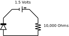
In this diagram, the diode is hooked up in the correct direction. This configuration is said to be forward biased. In this configuration, current will flow across the circuit. How much current? Well, according to Ohm’s Law:
1.5 Volts / 10000 Ohms = 0.15 MiliampsBut let’s check just to be sure… If we set our multimeter to amps, and we measure, we get… 0.1 Miliamps… …that doesn’t seem right…
Well, the bad news is that it is just one post into this series, and we’ve already come across an exception to Ohm’s Law. To figure out the current across a diode, we need to use the Shockley Ideal Diode Equation. Do yourself a favor: don’t waste your time trying to figure this out. Just use the Voltage/Amperage curve graphs provided on the datasheet for your diode and save yourself a headache.
Therefore, you will see a somewhat level amount of current flowing through your diode, then suddenly it will shoot up. If this happens, it’s time to consider that you need a different diode.
